Architectural Representation

Drawings, models and diagrams architects use to explain design. Every keyword shows its own picture beside a plain description — tap an image to see it up close.

Showing 25 of 25

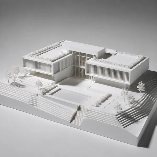
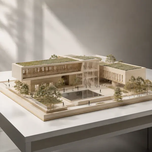
  • Physical Scale Model — Represents a building as a reduced three-dimensional object made from card, wood, plastic, or other materials
    01

    Physical Scale Model

    Represents a building as a reduced three-dimensional object made from card, wood, plastic, or other materials.

  • White Card Model — Uses plain white board to emphasize form, openings, massing, and shadow without material distraction
    02

    White Card Model

    Uses plain white board to emphasize form, openings, massing, and shadow without material distraction.

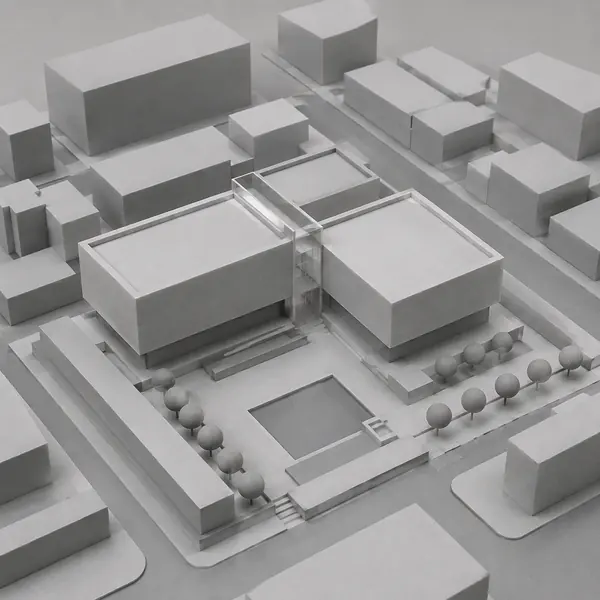
  • Massing Model — Simplifies a project into basic volumes to study height, scale, density, orientation, and site relationships
    03

    Massing Model

    Simplifies a project into basic volumes to study height, scale, density, orientation, and site relationships.

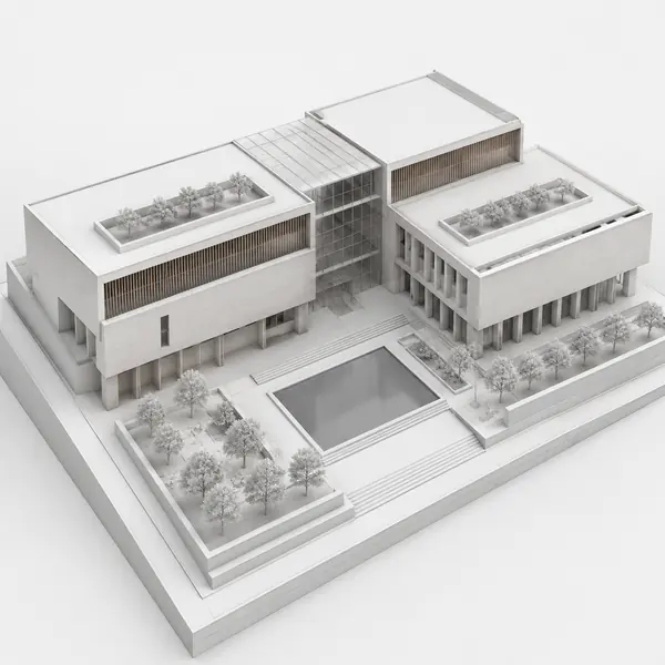
  • Digital 3D Model — Displays a computer-built three-dimensional design with controllable geometry, materials, views, and lighting
    04

    Digital 3D Model

    Displays a computer-built three-dimensional design with controllable geometry, materials, views, and lighting.

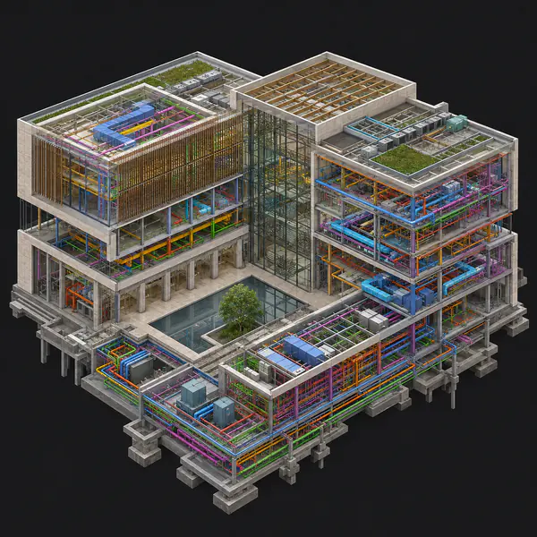
  • BIM Model — Shows a data-rich building model in which architectural, structural, and service components are coordinated
    05

    BIM Model

    Shows a data-rich building model in which architectural, structural, and service components are coordinated.

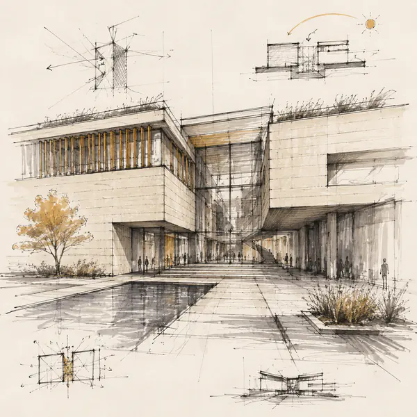
  • Concept Sketch — Communicates an early design idea quickly through loose lines, notes, shading, and simplified form
    06

    Concept Sketch

    Communicates an early design idea quickly through loose lines, notes, shading, and simplified form.

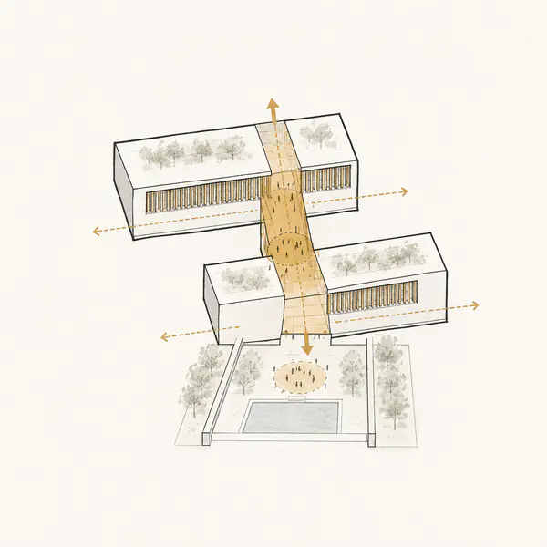
  • Parti Diagram — Reduces the main organizing idea of a project to a simple diagram of form, movement, hierarchy, or space
    07

    Parti Diagram

    Reduces the main organizing idea of a project to a simple diagram of form, movement, hierarchy, or space.

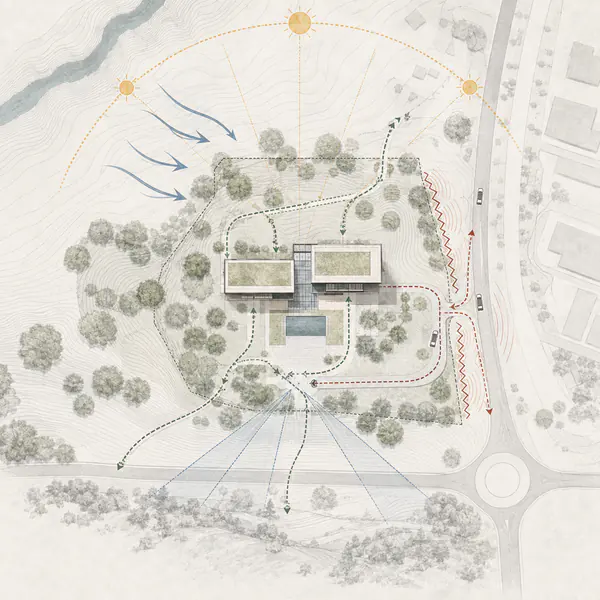
  • Site Analysis Diagram — Maps important site forces such as access, views, noise, climate, topography, vegetation, and surrounding uses
    08

    Site Analysis Diagram

    Maps important site forces such as access, views, noise, climate, topography, vegetation, and surrounding uses.

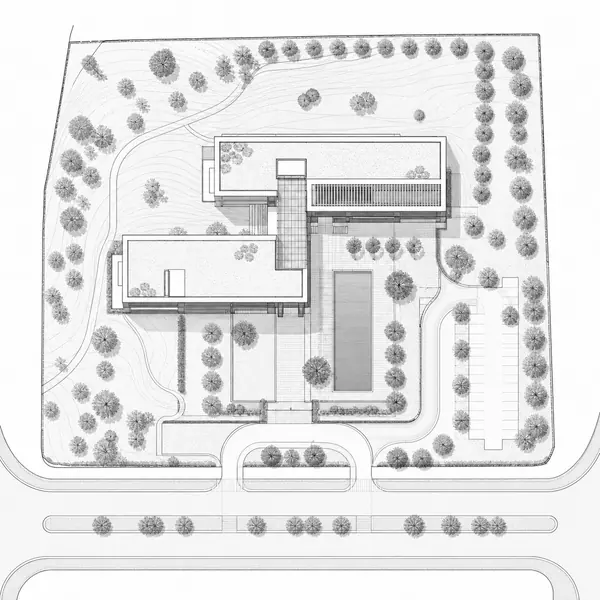
  • Site Plan — Shows the building footprint, property boundaries, roads, paths, planting, levels, and nearby context from above
    09

    Site Plan

    Shows the building footprint, property boundaries, roads, paths, planting, levels, and nearby context from above.

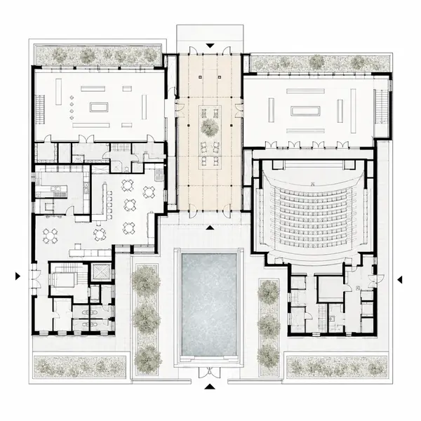
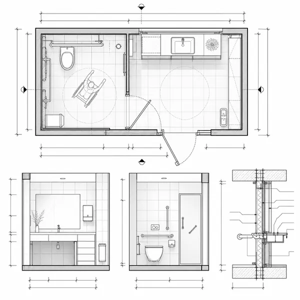
  • Floor Plan — Cuts horizontally through a building to show rooms, walls, doors, circulation, furniture, and dimensions
    10

    Floor Plan

    Cuts horizontally through a building to show rooms, walls, doors, circulation, furniture, and dimensions.

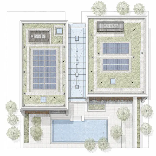
  • Roof Plan — Shows roof geometry, slopes, drainage, plant, skylights, terraces, parapets, and access from above
    11

    Roof Plan

    Shows roof geometry, slopes, drainage, plant, skylights, terraces, parapets, and access from above.

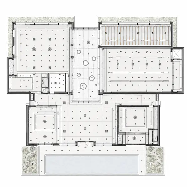
  • Reflected Ceiling Plan — Maps ceilings as if reflected onto the floor to show lighting, grids, bulkheads, diffusers, and detectors
    12

    Reflected Ceiling Plan

    Maps ceilings as if reflected onto the floor to show lighting, grids, bulkheads, diffusers, and detectors.

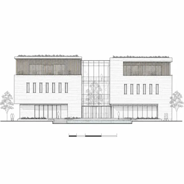
  • Elevation Drawing — Shows one exterior or interior face straight-on with levels, openings, materials, and vertical dimensions
    13

    Elevation Drawing

    Shows one exterior or interior face straight-on with levels, openings, materials, and vertical dimensions.

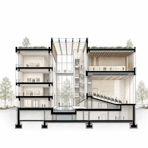
  • Building Section — Cuts vertically through a project to reveal floor levels, structure, spaces, height, and relationships between storeys
    14

    Building Section

    Cuts vertically through a project to reveal floor levels, structure, spaces, height, and relationships between storeys.

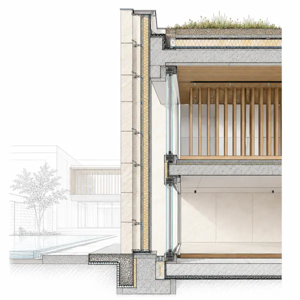
  • Wall Section — Enlarges a vertical slice through the envelope to explain layers, structure, insulation, finishes, and junctions
    15

    Wall Section

    Enlarges a vertical slice through the envelope to explain layers, structure, insulation, finishes, and junctions.

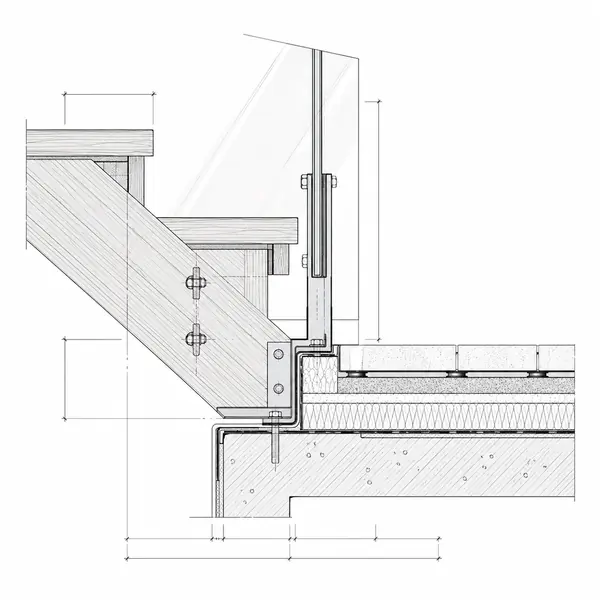
  • Detail Drawing — Explains a small construction condition at a large scale with precise materials, connections, and dimensions
    16

    Detail Drawing

    Explains a small construction condition at a large scale with precise materials, connections, and dimensions.

  • Construction Drawing — Provides coordinated technical information that contractors can use to build the project accurately
    17

    Construction Drawing

    Provides coordinated technical information that contractors can use to build the project accurately.

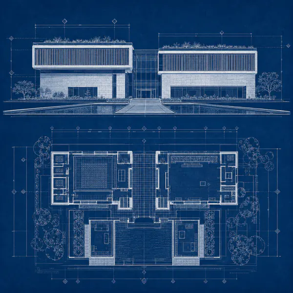
  • Blueprint Style — Presents technical linework in the familiar appearance of pale drawings on a deep blue background
    18

    Blueprint Style

    Presents technical linework in the familiar appearance of pale drawings on a deep blue background.

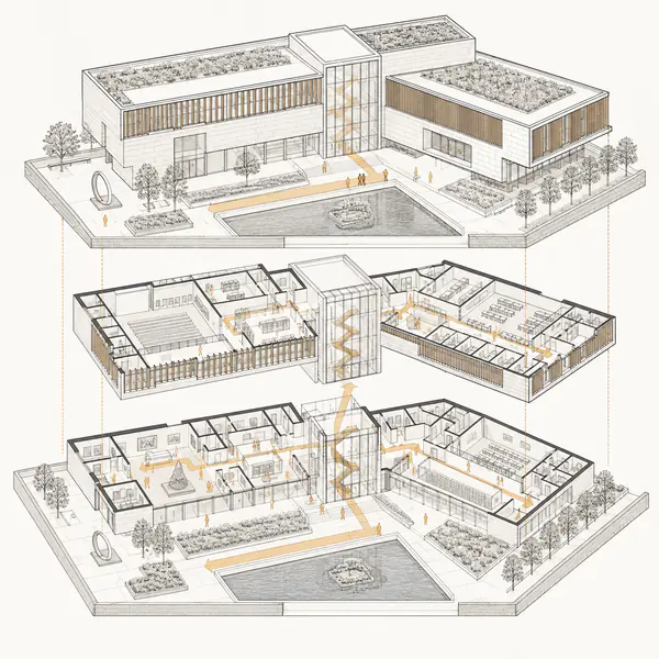
  • Axonometric Drawing — Shows three-dimensional form without perspective convergence so dimensions remain visually consistent along parallel axes
    19

    Axonometric Drawing

    Shows three-dimensional form without perspective convergence so dimensions remain visually consistent along parallel axes.

  • Isometric Drawing — Uses three equally scaled axes to present a clear measured-looking three-dimensional view
    20

    Isometric Drawing

    Uses three equally scaled axes to present a clear measured-looking three-dimensional view.

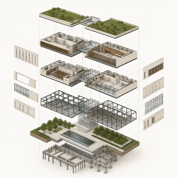
  • Exploded Axonometric — Separates floors, systems, or components vertically or horizontally while preserving their alignment and assembly order
    21

    Exploded Axonometric

    Separates floors, systems, or components vertically or horizontally while preserving their alignment and assembly order.

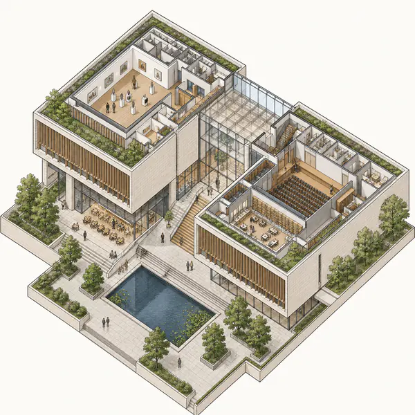
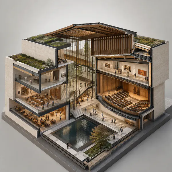
  • Cutaway View — Removes part of the exterior shell to reveal rooms, structure, or systems inside the building
    22

    Cutaway View

    Removes part of the exterior shell to reveal rooms, structure, or systems inside the building.

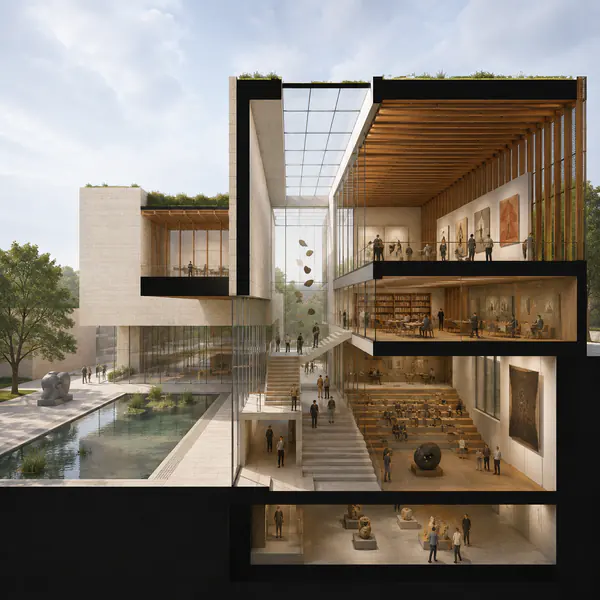
  • Section Perspective — Combines a sectional cut with realistic perspective depth to explain interior space and occupation
    23

    Section Perspective

    Combines a sectional cut with realistic perspective depth to explain interior space and occupation.

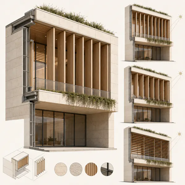
  • Facade Study — Examines the pattern, depth, materials, shading, openings, and modular logic of a building envelope
    24

    Facade Study

    Examines the pattern, depth, materials, shading, openings, and modular logic of a building envelope.

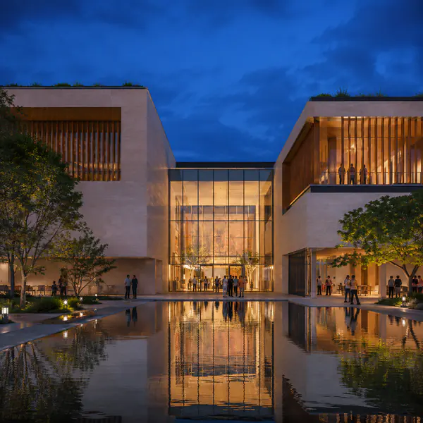
  • Photorealistic Architectural Render — Presents an unbuilt design with realistic materials, lighting, context, people, and camera behavior
    25

    Photorealistic Architectural Render

    Presents an unbuilt design with realistic materials, lighting, context, people, and camera behavior.